This page documents a modification I made to my J-PAC to allow me to pass power to my coin door lights using one of the wires in my JAMMA harness.
This method is strictly a pass-through arrangement. The J-PAC does not actually provide the power, you have to supply it from somewhere else, usually your PC.
The modification will work for +5v as well as +12v lights. Make sure you know what voltage your lights require before hooking any power up.
This modification assumes that JAMMA wire "F" is connected to your coin door lights. Your actual harness wiring may differ. If you'd like to supply power using a different JAMMA wire, modify the instructions accordingly.
WARNING: These modifications are not endorsed, encouraged, or authorized by Ultimarc. Modifying your J-PAC will will most likely void any warranty you have on it. Do not attempt if you are not skilled with a soldering iron. You are performing these modifications at your own risk and I will not be held responsible if you damage your J-PAC, yourself, your computer, or anything else that comes in contact with the J-PAC.
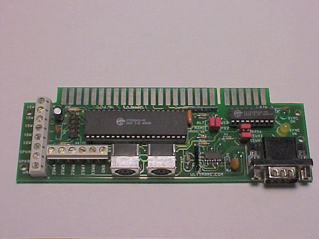
This is an unmodified J-PAC
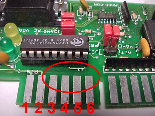
This is the "parts side" of the edge connector on the J-PAC that mates with your JAMMA harness. Notice that contacts 3,4,5,6 (used for JAMMA power) have no traces connected to them.
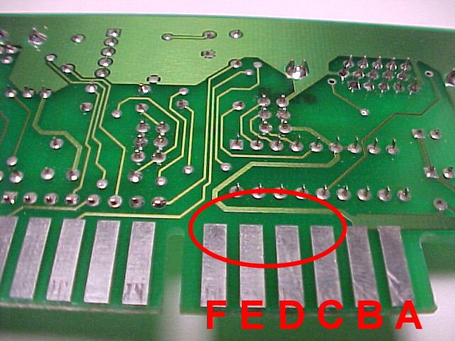
This is the "solder side" of the edge connector on the J-PAC that mates with your JAMMA harness. Notice that contacts C,D,E,F (used for JAMMA power) have no traces connected to them. According to Bob Roberts, you should use "F" in the JAMMA harness for +12v coin door power.
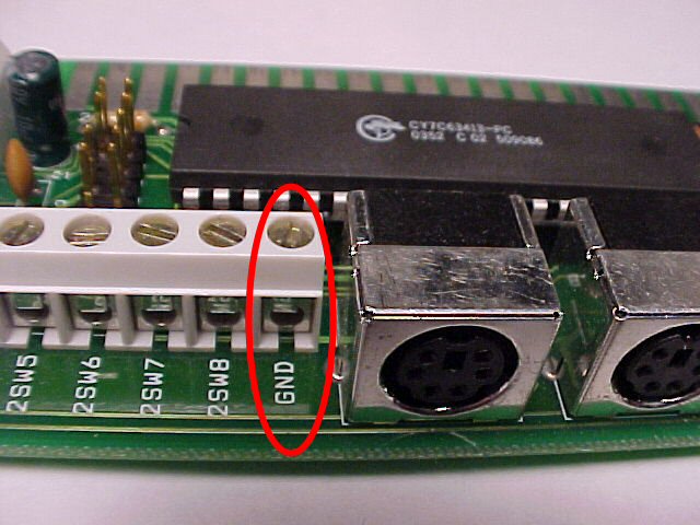
This is one of the ground wire screw terminals. There are two on the J-PAC. We want to use this one because as you'll see later, it is VERY easy to isolate it from the rest of the J-PAC circuitry.
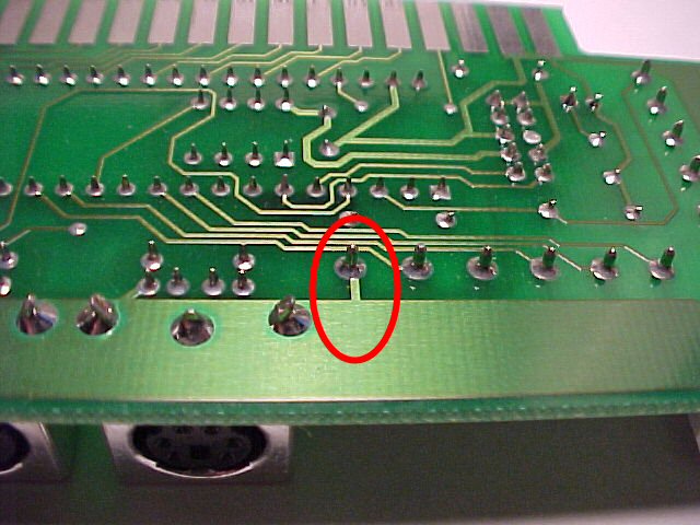
This is the solder side of the screw terminal pictured above. Notice that there is only a small circuit trace that connects the terminal to the larger grounding area.
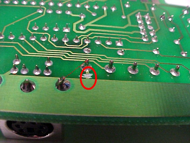
Carefully cut away a small section of the circuit trace, thereby isolating the screw terminal from the rest of the J-PAC. If you ever want to reverse this modification, you can simply solder a jumper wire between the pin and a ground point as indicated by the dotted red line in the picture.
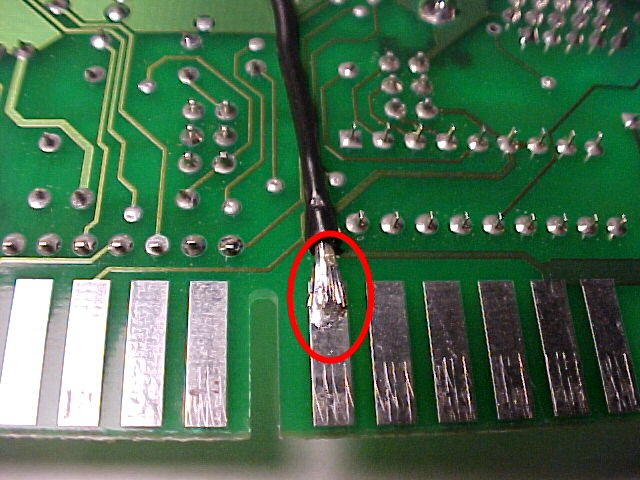
Tin the end of some 20 or 18 gauge wire and solder it to the edge of connector "F" on the J-PAC. Make sure that it is back far enough that it doesn't interfere with the JAMMA harness connector when it is plugged in.
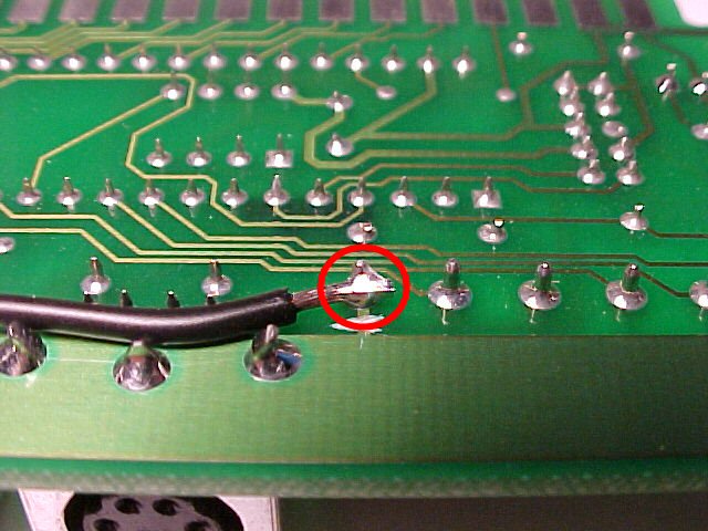
Then tin and solder the other end to the pin from the screw terminal that you liberated earlier.
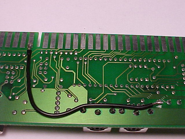
Here's the finished soldering job.
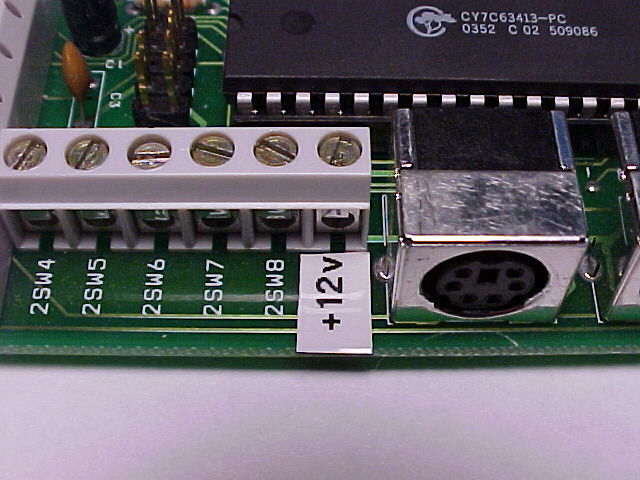
I re-labeled the top side to document the screw terminal's new purpose. Now just connect a powered 12v lead from your PC power supply (or another source) to the screw terminal and you're done!
Send your comments to: krick@3feetunder.com